Low Frequency Inverter Circuit Diagram Inverter Frequency Dc
Inverter as high voltage low current source circuit diagram Output frequency problem in inverter 13+ high frequency inverter circuit diagram
High Frequency Inverter Circuit Diagram
Operation of 200 watt inverter diagram How to make a powerful inverter using irfp460 mosfet & sg3525 with Inverter circuit power simple diagram low ic
200 watt inverter circuit
Low frequency three phases inverter4/5/6kw low frequency inverter output 120v 220v split inverter|reachpower 5kva ferrite core inverter circuit – full working diagram with4/5/6kw low frequency inverter output 120v 220v split inverter|reachpower.
A novel high frequency inverterHigh frequency inverter circuit diagram Simple low-power inverter circuit diagramMake simple 555 inverter circuit using mosfet.

Inverter circuit diagram 5kva pwm core ferrite sinewave homemade circuits sine solar board using working full transformer calculation details projects
Inverter frequency dc capacitor ups circuit link diagram voltage rectifier high bus three motor phase ceramic using transformer intermediateLow voltage frequency inverter 8-12kw low frequency inverterInverter frequency high diagram circuit power 500w source.
The topology of high-frequency inverter with parasitic elements5kva ferrite core inverter circuit Cp-low frequency inverterInverter parasitic topology.

Diagram block inverter watt inverters 200watt operation circuits control eleccircuit output electronic projects two figure
Frequency inverter circuit diagramInverter principle Low frequency inverter 4-6kw with mpptWhich is better low frequency or high-frequency inverter?.
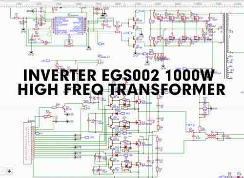
Microtek digital inverter circuit diagram1000w inverter 12/24vdc to 220vac with egs002 high frequency Frequency inverter circuit diagram8-12kw low frequency inverter.

Inverter frequency 100w pcb schematics
Inverter smps frequency improved based high factor power figureFrequency inverter low customer high feedback another here inside High frequency inverter circuit diagramWhy customer needs low frequency inverter to replace his high frequency.
Inverter 1000w egs002 220vac 24vdc pdf pcb transformer freqHigh frequency inverter circuit diagram – artofit Inverter mosfet ne555 using power circuit volts 220 555 diagram ic simple make timer wave output 50hz use frequency generatorInverter voltage high current low source circuit diagram 555 timer power ic using schematics circuits full electronic labels.
What is a high-frequency power inverter?
Low inverterHigh frequency smps based inverter with improved power factor Low‐frequency equivalent circuit of the proposed inverterWhat is a frequency inverter?.
Low frequency inverter 3000w 12v low frequency pure sine waveHigh frequency inverter circuit diagram .


